PLANNING & RESOURCES
Center Configuration
When designing a new building, the structure should ideally have a clear span in the bowling equipment area. The ceiling height should be at least 3.50 metres (11’6”). Bowling centers require a specific heating, air conditioning and electrical specification. It is strongly recommended to discuss these requirements with Switch® and your architect or contractor, before proceeding.
Building Size
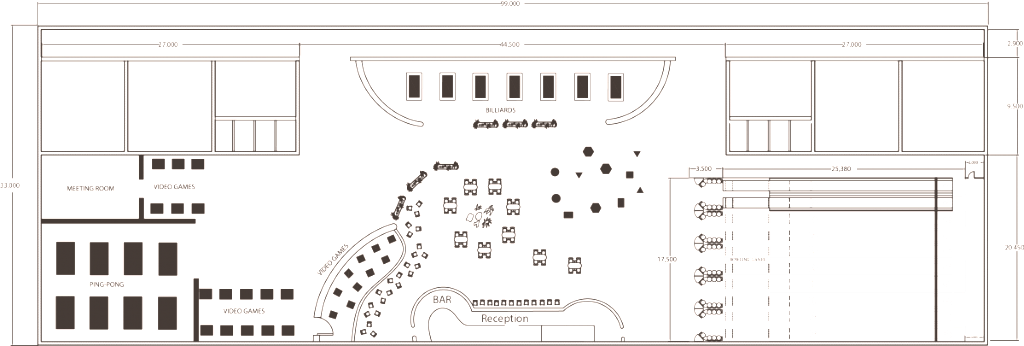
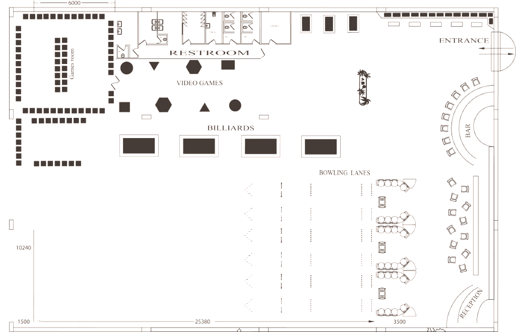
To determine the size of the building, use the lane width chart (in the next section) once you have selected the number of lanes you are intending to install. You should then decide what other facilities you would like to provide, such as reception, snack bar, arcade machines, cafeteria, children’s area, billiards and party rooms. Within the limits of the possibilities, always include side aisles, otherwise known as service aisles, on each side of the bowling lanes. We recommend one metre aisles, however this is often dictated by the proposed available area.
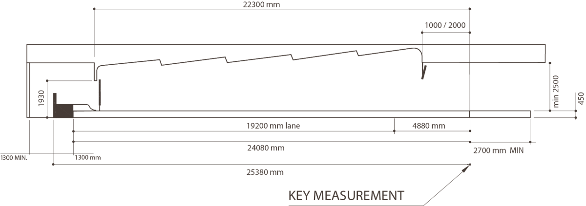
The length is determined by using the length of the bowling lanes (25.38m— 83’ 3 1/4''), including the machines, lanes and approach. Then add a recommended (1.50m— 59'') clear service passage behind the pinsetters and finally add a minimum of 4.0m— 13'2'' for a standard bowlers seating area. For the seating area—and depending on the environment being created—Switch® offers a variety of modular arrangements to help you with a unique configuration, according to the specifications that you and your architect have, and as the space allows.
Bowling Lane Widths

The following dimensions are net measurements of uninterrupted lane widths only. Additions should be made for columns, walls, and passages between or beside lanes.
Number of Uninterrupted Lanes
Minimum Width
(cm)
Minimum Width
(in)
2
3.46m
11'6"
4
8.85m
22' 7 1/4"
6
10.24m
33' 8 1/2"
8
13.63
44' 9 3/4"
10
17.02
55' 11"
12
20.41
67' 1/4"
14
23.80
78' 1 1/2"
16
27.19
89' 2 3/4"
18
30.58
100' 4"
20
33.97
111' 5"
Number of Uninterrupted Lanes
Minimum Width
(cm)
Minimum Width
(in)
22
37.36
122’ 6 1/2”
24
40.75
133’ 7 3/4”
26
44.14
144’ 9”
28
47.53
155’ 10 1/4”
30
50.92
167’ 11 1/2”
32
54.31
178’ 3/4”
34
57.70
189’2”
36
61.09
200’ 3 1/4”
38
64.48
211’ 4 1/2”
40
67.87
222’ 5 3/4”
Columns in the Lane or Bowlers’ Area
Where supports for the structure above the lane are necessary, it is desirable to use a minimum lateral spacing between columns of 6.89 m (22’ 7”) per four lane bay plus 2.54 cm (1”) for clearance to reduce noise transmission. The 4.91 m (16’) approach area and at least 0.61 m (2’) beyond the foul line should be kept free of columns, if possible.
Floor Loadings
The floor loading values are approximately as follows :
Approach Area
– 2KN/m2 (Up to 4,90metres from the start of the Approach)
Lane Area – 1KN/m2 (From 4,90 metres to the Curtain Wall)
Machine Area
(All the remaining area behind the Curtain Wall) The rear pin elevator of the pinsetters rests on 4x25mm Jack screws. The floor must be able to support a loading of 175Kg. It is recommended that the floor be “Float Finished” , and a suitable concrete sealer, paint or linoleum be applied to stop the generation of dust, and to assist with the general maintenance of this important part of the bowling center.
Second Floor Installation
If lanes are to be installed on the second floor or higher, you must provide a floor strong enough to carry the load of the bowling equipment and public occupancy. Consider the noise in the spaces below and adjacent to the lanes. Soundproofing may be required, please ask for further details. Your floor must be constructed to limit vibration. It is the customer’s responsibility to provide all access machinery needed to move the Bowling equipment into the desired area (i.e cranes, lifts, ramps Etc).
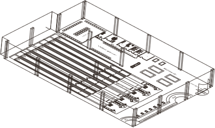
I-BEAM Foundation (TRUSS JOIST)
The foundation uses I-BEAM technology and can be installed very quickly.
The I-beams run at 90° to the lanes.
Approach to Bowlers Concourse
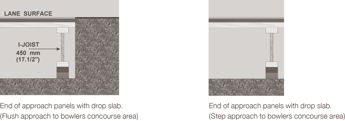
Seating Area
It is the customer’s responsibility to supply the seating area and all steps up or down on to it. Switch® Technicians will install the seating and scoring equipment at the appropriate times. Dependent on the design and available space, the seating area can be flush to the approach or a step (height dependent on local authority regulations). A step can provide a demarcation between areas and also help against the travel of dirt. However, a flush seating area to approach is advantageous with disabilities, and will require no maintenance in the future but will require a specialist demarcation strip.
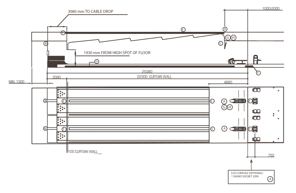
Scoring Installation
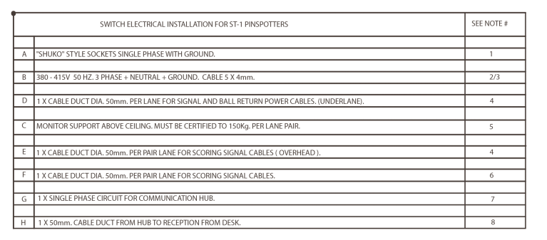
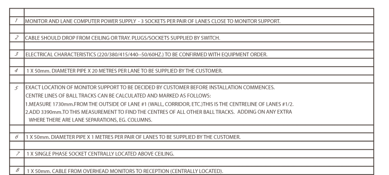
The Switch® Pinsetter uses 3-phase power on all motors. Local Voltage and Frequency (380V/50 hertz, 415V/50 hertz, 220V/60hertz, etc.) must be established before the order is placed. The Electrical Installation of the Switch® Pinsetter is designed to be simplified, since one 5-core cable per pair of lanes is all that is required for the Pinsetter and Ball Return installation. The power supply to the Ball Lift (bowlers end) & the Foul Detector is also included in the Switch® Pinsetter control box.
However, it is the responsibility of the customer to provide 2 X 50mm diameter plastic pipes, for under lane cabling and wiring for each pair of lanes (scoring, signal and ball return power cables). The pipes will be approximately 20 metres long, and be placed one on each side of the ball track. The pipes will be installed by the Switch® technicians during installation (effectively 1x20 metres pipe per lane) .
The Switch® Pinsetter Control Box is fitted with the following safety features :
-- Overload Protection - Each pinsetter has its own circuit breaker incorporated.
-- Residual Current Device - (Earth Leakage protection). Each pinsetter circuit breaker is controlled by an RCD to ensure that the risk of electric shock is kept to a minimum.
-- Minimum Voltage Monitor - Since 3-Phase motors are used in the Pinsetter, a special circuit has been provided to protect against the damage that could be caused, if for any reason there is an unacceptable imbalance between the 3 phases, an imbalance occurs or a phase is lost completely, the power is automatically disconnected.
All protection against potential danger overload, earth leakage, and unacceptable phase imbalance, is included in the Switch® Pinsetter control box, reducing the cost of the electrical installation, since these features do not have to be provided in the Main Distribution Panel for the Pinsetters. A “General Circuit Breaker” or Isolator for each group of 6 to 8 lanes is sufficient. One 5-core (5 x 4mm2- 3 phase + neutral + ground) is all that is required per pair of lanes. The cable should be installed above the Pinsetters, at approximately 3 metres behind the Curtain Wall, above the Pinwheels.
Pinsetter Power Requirements
Structural
A suitable support for the overhead monitors should be installed to hold approx 150 Kilos per pair of monitors. We are happy to advise in the positioning of the support however this work should be carried out prior to the arrival on site of the Switch® installation crew. Your Architect needs to certify the loading capacity.
Electrical
Overhead Monitors
– A dedicated two gang 220v -240v power supply is required per pair of monitors in line with the centre of the ball return tracks in the ceiling.
Bowlers Console – The power is supplied by the Switch® Scoring System for the standard keyboard console, however if the touch screen monitors are ordered, a dedicated two gang 220v - 240v power supply is required at the “Bowlers Consoles” in the seating area. Cable conduits should be prepared below the finished floor at the bowlers’ seating area.
Front Desk
– The equipment supplied requires six two gang 220v - 240v dedicated supplies, it is recommended to discuss the positioning with the customer, architect, contractors & Switch® before installation. In addition to the power supply, a dedicated ADSL / Broadband phone line should be installed beside the front desk for software help, updates, general remote maintenance & support.
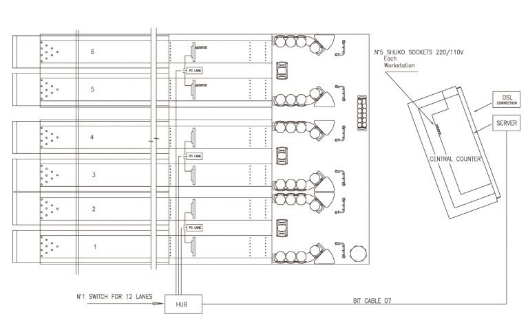
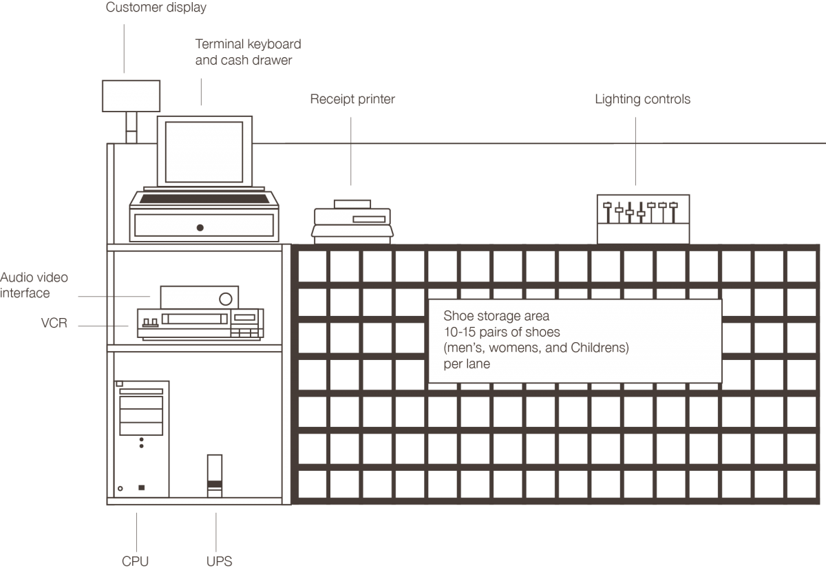
Typical Front Desk Layout
The front desk is one of the most important areas of the bowling centre. Dependent on the Switch® package ordered, the amount of space required, and also the amount of time each customer will need to be at the front desk will be affected, (for example, no bowlers console means names will be required at the time of check in).
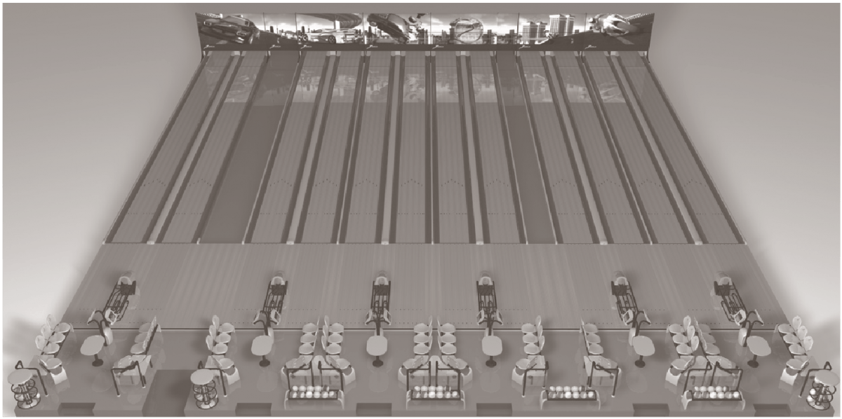
Lighting over Lanes and Approach Area
It is critical to ensure proper lighting is installed over the Bowling equipment to create the desired environment with no shadow being created, especially in the lane area, which is a highly reflective playing surface. Extreme care must be taken to avoid “Hot Spots” of light, a standard “Saw Tooth” (Suspended Ceiling) arrangement usually prevents the effects of “Hotspots” The lighting system should be installed with as much built in flexibility as possible to enable “mood” changes at designated times during the trading hours. Remember, different areas will need specific lighting levels, front entrance, bar, games areas etc. All Switch® equipment and the lanes are UV reactive. Black (UV) lighting installed creates a stunning glow effect, the more UV applied the greater the effect. (Rule of thumb – Match UV (black) with the same amount of White). The glow lanes lend themselves to enhanced special effects lighting including Disco lighting effects. Your Switch® representative can advise on suitable Sound and Light Systems. It is best to control lane lighting longitudinally switched in banks of 4 lanes, from the control desk, with the special effects lighting across the house. Do not forget to include in your planning a high quality Acoustic Sound System, for creating the moods through music, customer announcements and general information transmissions. All modern facilities need to be designed with the acoustics having been given careful consideration, to create that quality feeling.
Power Consumption
The power consumption of a pair of lanes is a maximum of 4 KW, assuming that all motors are running at the same time. This is not the case during operation. However, the Sweep and Table motors run intermittently. Based on this calculation, a 48 lane facility would theoretically require the provision of 96 KW, but in practice it would be less, due to the intermittent operation of the motors.
Bowling Area Pre-installation
All overhead works above the Bowling installation must have been completed. For example; lighting, ceilings, alarm systems, air conditioning, ducting, electrical cable trays etc. Also supports for Switch® scoring monitors and all electrical installation. No “Wet Trades” (plasterers, bricklayers, and decorators etc.) are to be working in the immediate area of the Bowling installation.
Temperature and Humidity
These controls must be in place, either by the completion of the permanent air conditioning system, or by the provision of temporary equipment. Temperature and Humidity levels must be consistently maintained as close as possible to those of the conditions foreseen for the future operation of the Bowling Centre. In any case, the temperature and humidity levels during Lane installation must be within the following limits:
Temperature
– Temperature should be maintained between 16 and 23 degrees Celsius.
Humidity
– Humidity should be between 40% and 60% Relative Humidity.
Switch® declines any responsibility for any movement and/or distortion of synthetic lane panels subjected to ambient temperatures and humidity levels out with the above limits. In the event that lane panels have to be stored on site, or elsewhere, for long periods, it is important that prior to installation, the panels are given sufficient time to re-stabilise to the ambient conditions on the installation site. In the event that other construction work has to be carried out in the immediate area of the Bowling installation, the Bowling area should be sealed off by polythene sheeting so that ambient temperature and humidity can be kept constant.
A Reliable Power Supply – Reliable power should be made available to the Switch® installation crew for power tools at no charge. An area in which to store Switch® specialist installation tools is also required.
Typical Six Lane Layout
Typical Ten Lane Layout